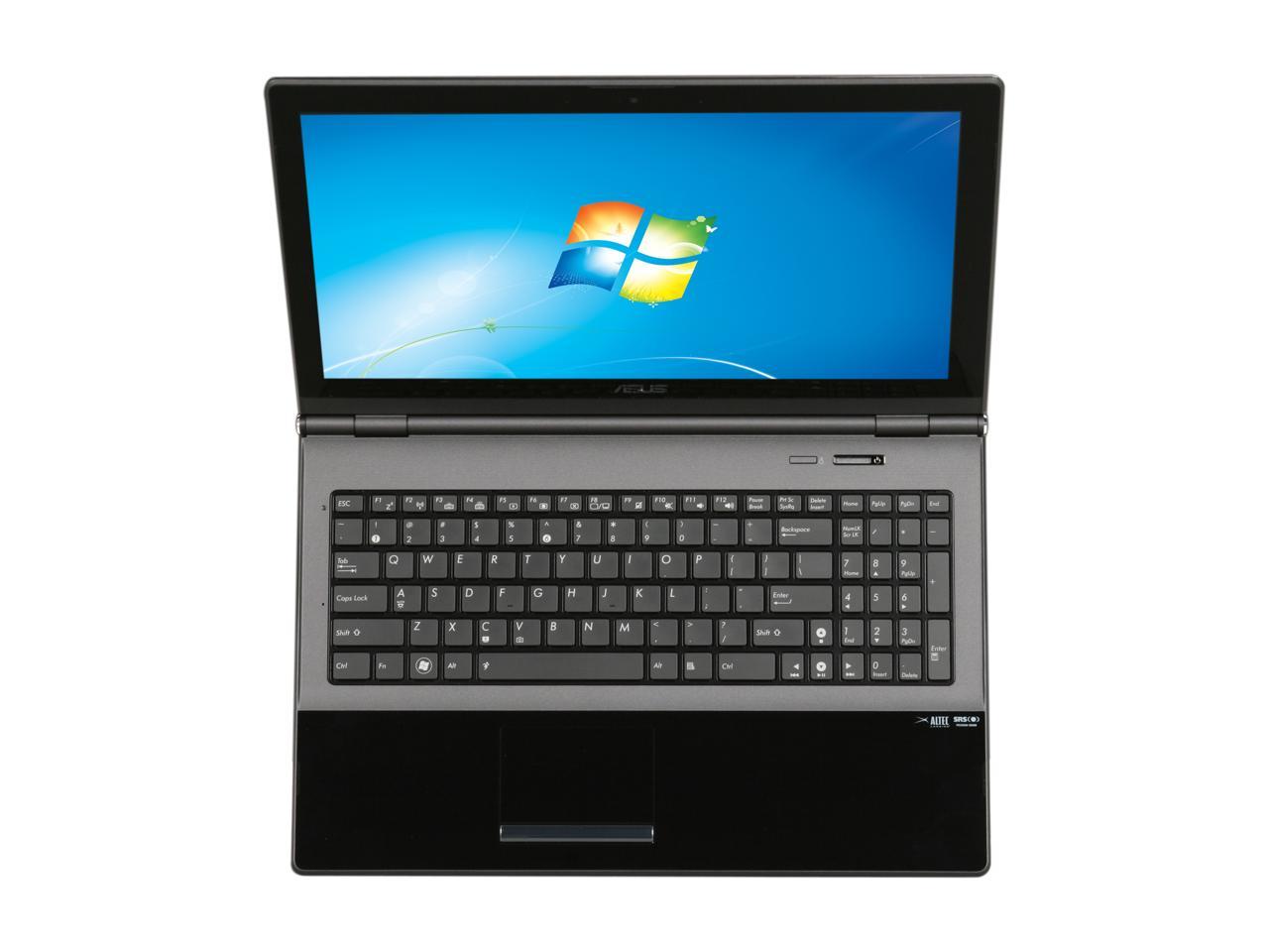
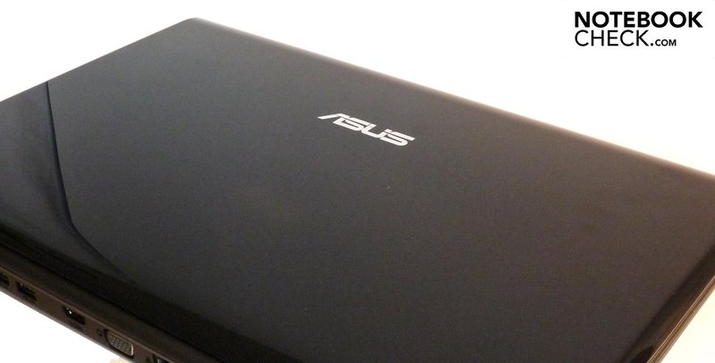
In this guide I will disassemble an Asus UX50V laptop.
- Ux50v Laptops & Desktops Driver Download For Windows 10 64-bit
- Ux50v Laptops & Desktops Driver Download For Windows 10
- Ux50v Laptops & Desktops Driver Download For Windows 10 Laptop
- Ux50v Laptops & Desktops Driver Download For Windows 10 32-bit
- Ux50v Laptops & Desktops Driver Download For Windows 10 Windows 7
Asus UX50V laptop review Asus has been focusing on the design of its products of late and the UX50V is certainly a looker, but does it have the brains to match this beauty? By: Mike Jennings. I recently updated the graphics drivers in my asus ux50v laptop from 186 to the newest (280 something i think) and now the computer keeps telling me that the display adapter isnt connected. When i go into device manager it shows that the geforce g105m is connected and is running the newest drivers. View full Asus UX50V-RX05 specs on CNET. ASUS CopyProtect, ASUS Fancy Start, ASUS LifeFrame3, ASUS Live Update, ASUS MultiFrame, ASUS Net4Switch, ASUS Power4 Gear eXtreme, ASUS SmartLogon, ASUS. Hello, My ASUS UX50V Laptop battery keeps dying and won't charge at first I thought it was a bad battery but then I went and bought a new one and it did the same thing twice any help as to what the problem may be why its not charging the battery???
I’m not sure 100% but I think this guide might work for one of the following Asus models: U50A, U50F, U50VG, U50, U50V, U50F, U50VF.
If you have one of the mentioned models please confirm if my guide works (of doesn’t work) for you in comments after this post.
I’ll go through the following major disassembly steps:
STEP 1-7: Disconnecting and removing the keyboard.
STEP 8-11: Removing the top cover and display assembly.
STEP 12-18: Removing the DVD drive, hard drive and cooling fan.
STEP 19-21: Removing the motherboard and accessing both memory modules.
STEP 1.
Turn off the computer. Remove the battery.
STEP 2.
The keyboard is secured to the top cover by five plastic latches.
Push on a latch with a small flathead screwdriver and at the same time lift up the keyboard a little bit.
When the keyboard is lifted up, it will not allow the latch to lock.
Unlock all five latches.
STEP 3.
Now you should be able to lift up the upper side of the keyboard and turn it upside down.
Be careful, there are two ribbon cables connected the keyboard to the motherboard.
It’s necessary to unlock both connectors and release cables before removing the keyboard.
In the following three steps I explain how to unlock connectors.
STEP 4.
Here’s the main keyboard cable connector and it’s shown in the locked position.
Slide the locking tab (brown piece) about 1-2 millimeters to the shown direction.
NOTE: the locking tab must stay attached to the connector base.
STEP 5.
On this picture the same connector shown in the unlocked position.
Now you can pull keyboard cable from the connector.
STEP 6.

Unlock the keyboard backlight cable connector same way as the main connector.
Release and remove the cable.
STEP 7.
Remove the keyboard.
STEP 8.
Remove all screws from the bottom.
STEP 9.
Remove screws securing the top cover assembly.
Disconnect the following cables:
1. Touchpad cable.
2. Video cable.
3. Web camera cable.
4. Power button board cable.
Also, it’s necessary to disconnect wireless card antenna cables from the wireless card.
Here’s how to disconnect wireless card antenna cables.
Simply lift up the golden connector and unplug it from the card.
Disconnect the touchpad cable the same way we disconnected the keyboard cable in steps 4 and 5.
Slide the locking tab about 1-2 millimeters to the shown direction.
After that pull the cable from the connector.
In order to disconnect the video cable, just pull it up by the clear tab attached to the connector.
Finally, disconnect the web camera cable and power button board cable.
These are regular male-female connectors.
STEP 10.
After all screws removed and cables disconnected you can start separating the top cover assembly from the bottom cover.
I’m using the guitar pick as a case cracker. You can use a small piece of soft plastic. Insert it between the top cover and bottom cover and move slowly along the side.
Ux50v Laptops & Desktops Driver Download For Windows 10 64-bit
At the same time lift up the top cover with your finger.
STEP 11.
Lift up and remove the top cover assembly.
As you see, the display panel attached to the top cover. Remove them together.
STEP 12.
This is a view on the bottom part of the top cover assembly.
Here you can access the power button board and touchpad.
This is a view on the laptop internal components after the top cover/display assembly removed.
STEP 13.
Remove three screws securing the hard drive assembly.
STEP 14.
Lift up the hard drive assembly and disconnect it from the cable.
STEP 15.
Remove four screws securing the DVD drive.
STEP 16.
Lift up one side of the DVD drive and slide it to the shown direction to disconnect from the motherboard.
Remove DVD drive.
STEP 17.
Remove two screw securing the cooling fan.
Disconnect fan cable from the motherboard.
STEP 18.
Lift up and remove the cooling fan.

STEP 19.
Remove screws securing the motherboard.

Disconnect the touchpad cable.
STEP 20.
Carefully lift up one side of the motherboard and remove it from the bottom base.

The motherboard removed.
STEP 21.
Here’s a view on the bottom side of the motherboard.
NOTE: in an Asus UX50V laptop both memory modules are located on the BOTTOM side of the motherboard. In order to remove, replace or upgrade memory it’s necessary to disassemble the entire laptop and remove the motherboard.
Here’s a view on the bottom cover with the motherboard removed.
Here you can access:
– Card reader board.
– CMOS battery (attached to the card reader board).
– USB board.
– Touchpad button board.
– Both speakers.
In this guide I will disassemble an Asus UX50V laptop.
I’m not sure 100% but I think this guide might work for one of the following Asus models: U50A, U50F, U50VG, U50, U50V, U50F, U50VF.
If you have one of the mentioned models please confirm if my guide works (of doesn’t work) for you in comments after this post.
I’ll go through the following major disassembly steps:
STEP 1-7: Disconnecting and removing the keyboard.
STEP 8-11: Removing the top cover and display assembly.
STEP 12-18: Removing the DVD drive, hard drive and cooling fan.
STEP 19-21: Removing the motherboard and accessing both memory modules.
STEP 1.
Turn off the computer. Remove the battery.
STEP 2.
The keyboard is secured to the top cover by five plastic latches.
Push on a latch with a small flathead screwdriver and at the same time lift up the keyboard a little bit.
When the keyboard is lifted up, it will not allow the latch to lock.
Unlock all five latches.
STEP 3.
Now you should be able to lift up the upper side of the keyboard and turn it upside down.
Be careful, there are two ribbon cables connected the keyboard to the motherboard.
It’s necessary to unlock both connectors and release cables before removing the keyboard.
In the following three steps I explain how to unlock connectors.
STEP 4.
Here’s the main keyboard cable connector and it’s shown in the locked position.
Slide the locking tab (brown piece) about 1-2 millimeters to the shown direction.
NOTE: the locking tab must stay attached to the connector base.
STEP 5.
On this picture the same connector shown in the unlocked position.
Now you can pull keyboard cable from the connector.
STEP 6.
Unlock the keyboard backlight cable connector same way as the main connector.
Release and remove the cable.
STEP 7.
Remove the keyboard.
STEP 8.
Remove all screws from the bottom.
STEP 9.
Remove screws securing the top cover assembly.
Disconnect the following cables:
1. Touchpad cable.
2. Video cable.
3. Web camera cable.
4. Power button board cable.

Also, it’s necessary to disconnect wireless card antenna cables from the wireless card.
Here’s how to disconnect wireless card antenna cables.
Simply lift up the golden connector and unplug it from the card.
Disconnect the touchpad cable the same way we disconnected the keyboard cable in steps 4 and 5.
Slide the locking tab about 1-2 millimeters to the shown direction.
After that pull the cable from the connector.
In order to disconnect the video cable, just pull it up by the clear tab attached to the connector.
Finally, disconnect the web camera cable and power button board cable.
These are regular male-female connectors.
STEP 10.
After all screws removed and cables disconnected you can start separating the top cover assembly from the bottom cover.
I’m using the guitar pick as a case cracker. You can use a small piece of soft plastic. Insert it between the top cover and bottom cover and move slowly along the side.
Ux50v Laptops & Desktops Driver Download For Windows 10
At the same time lift up the top cover with your finger.
STEP 11.
Lift up and remove the top cover assembly.
As you see, the display panel attached to the top cover. Remove them together.
STEP 12.
This is a view on the bottom part of the top cover assembly.
Here you can access the power button board and touchpad.
This is a view on the laptop internal components after the top cover/display assembly removed.
STEP 13.
Ux50v Laptops & Desktops Driver Download For Windows 10 Laptop
Remove three screws securing the hard drive assembly.
STEP 14.
Lift up the hard drive assembly and disconnect it from the cable.
STEP 15.
Remove four screws securing the DVD drive.
STEP 16.
Lift up one side of the DVD drive and slide it to the shown direction to disconnect from the motherboard.
Remove DVD drive.
STEP 17.
Ux50v Laptops & Desktops Driver Download For Windows 10 32-bit
Remove two screw securing the cooling fan.
Disconnect fan cable from the motherboard.
STEP 18.
Lift up and remove the cooling fan.
STEP 19.
Ux50v Laptops & Desktops Driver Download For Windows 10 Windows 7
Remove screws securing the motherboard.
Disconnect the touchpad cable.
STEP 20.
Carefully lift up one side of the motherboard and remove it from the bottom base.
The motherboard removed.
STEP 21.
Here’s a view on the bottom side of the motherboard.
NOTE: in an Asus UX50V laptop both memory modules are located on the BOTTOM side of the motherboard. In order to remove, replace or upgrade memory it’s necessary to disassemble the entire laptop and remove the motherboard.
Here’s a view on the bottom cover with the motherboard removed.
Here you can access:
– Card reader board.
– CMOS battery (attached to the card reader board).
– USB board.
– Touchpad button board.
– Both speakers.
